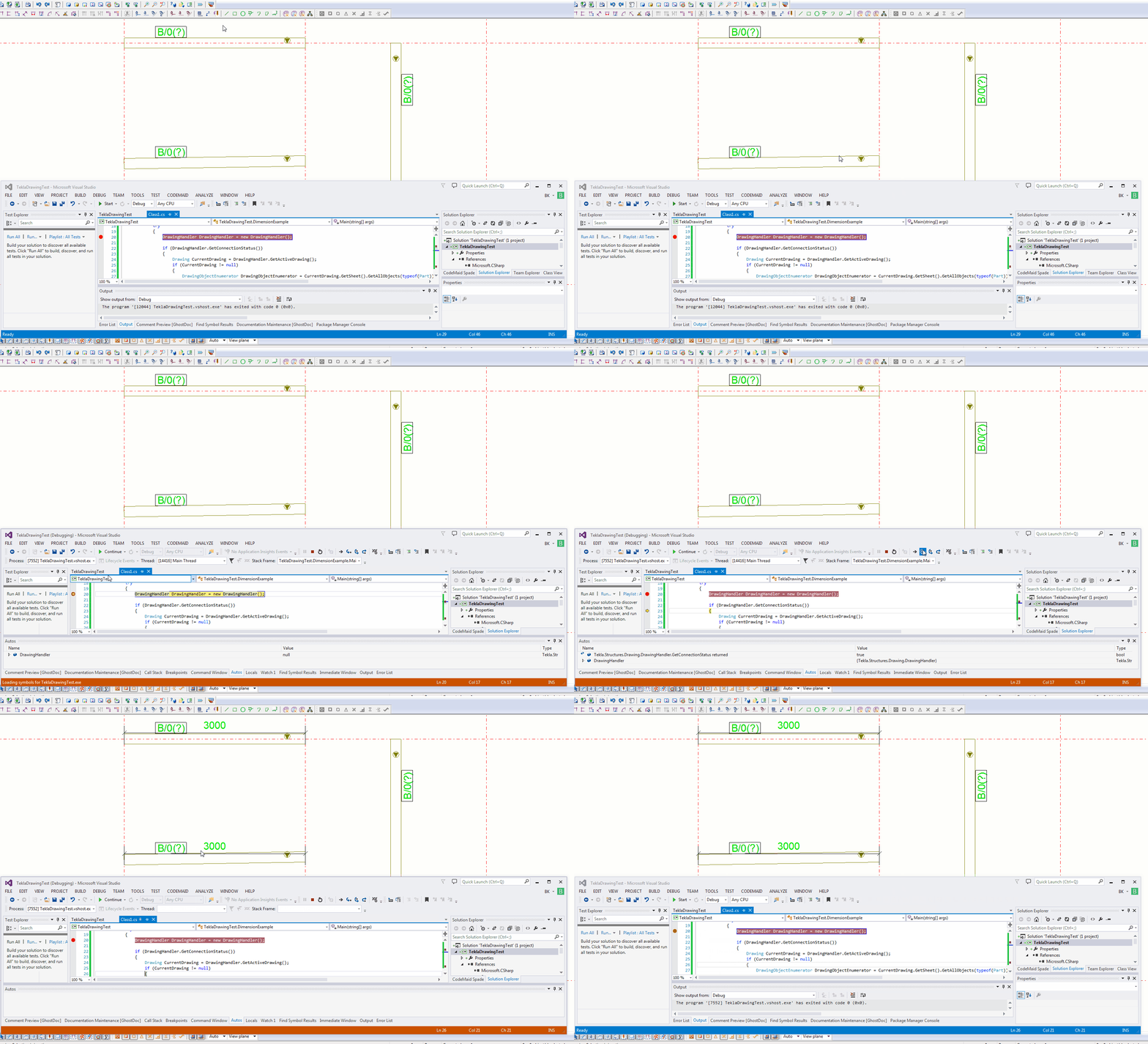
This is an example of a hello world program which dimensions a beam. I found this code in the Tekla Drawing Samples folder.
You can see it in action here:

Let’s walk through it:
- We have to get the relevant drawing.
- Then we have to get the relevant part we want to dimension.
- Then we get the view associated with the part.
- We save our current transformation plane, and we set a new transformation plane to the particular view’s display coordinate system.
- From here, get the part’s identifier and we select the ModelObject in the model itself – to get the relevant coordinates of the Beam we want to dimension.
- Once we’ve used the identifier to get the Beam we are after, and to get it’s relevant parts then we create the dimension.
- Remember to save back the original transformation plane.
- Note: if you insert the dimension then I obtained an exception. I don’t think you need to insert dimensions when working on drawings.
- Note 2: if you forget to save the transformation plane back to the original, then you will find that you dimensions will go wacky, next time you run the command. Always remember to leave things as you found them!
- Note 3: You have to have the beam in the same plane as your view otherwise it won’t draw the dimension.
Here is the code for your benefit:

Leave a Reply