Tag: steel detailing

  • Understanding PFC Shear Connection: A Practical Discussion

    Understanding PFC Shear Connection: A Practical Discussion


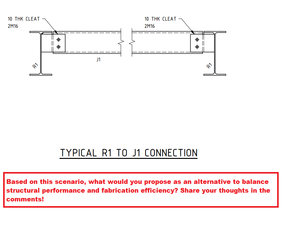
    Based on this scenario, what would you propose as an alternative to balance structural performance and fabrication efficiency? Share your thoughts in the comments!

    Introduction

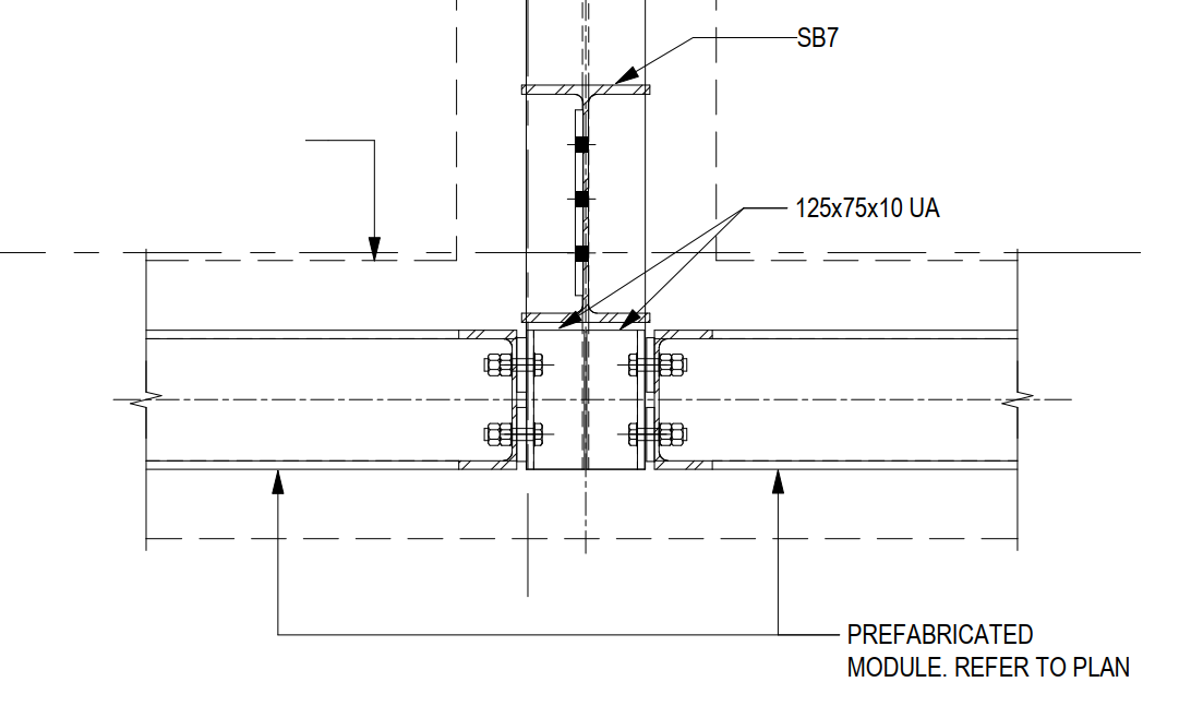
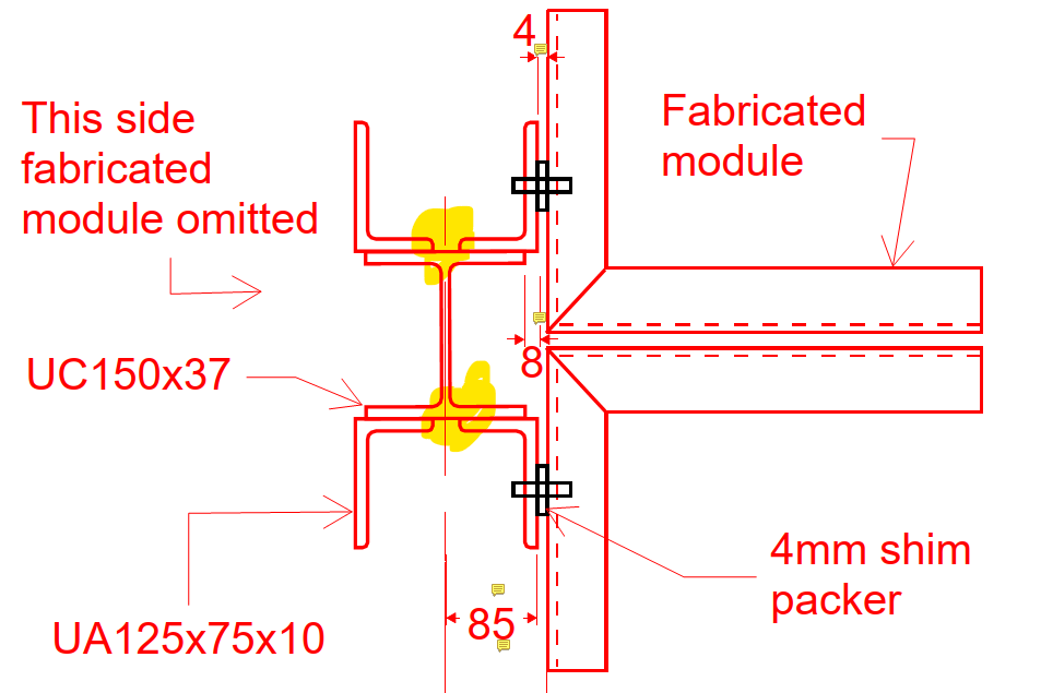
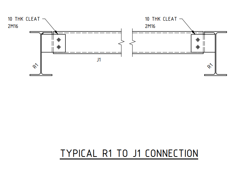
    Shear connections play a crucial role in structural steelwork, ensuring the stability and strength of a framework. One common method is the extended shear plate connection, as seen in the R1 to J1 connection detail. However, this method introduces bolt eccentricity, which could impact the overall efficiency of the joint.

    The Challenge

    In the given design, the PFC (Parallel Flange Channel) shear connection is detailed using an extended shear plate. While this is a standard approach, it inherently results in increased eccentricity due to the offset load transfer through the bolts. This can lead to additional bending moments in the connection, requiring careful consideration in the design phase.

    Possible Solution

    A potential improvement is to introduce a cope in the PFC section and utilize a simple shear connection instead. This modification would:

    • Reduce bolt eccentricity
    • Simplify force transfer
    • Enhance structural performance

    However, this approach was not accepted by the client due to fabrication ease considerations.

    Key Learning for Junior Engineers

    This case highlights a key engineering principle: design optimization vs. fabrication practicality. While structural efficiency is paramount, practical considerations such as ease of fabrication, cost, and site constraints often dictate final design choices.

  • Erection Issue Eliminated Through Suggested Changes in the Splice Connection During Detail Engineering

    Erection Issue Eliminated Through Suggested Changes in the Splice Connection During Detail Engineering

    Issue Identified During Detail Engineering

    • During detail engineering, it was identified that the design specifies both-side web plates, with shop weld on one side and field bolts on the other.
    • This would have created a field erection issue, as the shop-welded web plate on both sides prevents secondary beam placement.

    Proposed Solution: Fully Bolted Connection

    • Use bolted connections on both sides instead of welding one side.
    • This allows the web plate to be shipped loose, making field installation easier.
    • At the site, the secondary beam can be placed first, followed by the web plate installation and bolting.
    • Factory-drilled holes ensure precise alignment and better quality.
    • Eliminates on-site welding hazards and inspection issues.

    Client Approval

    • The client accepted the suggestion due to its practical benefits and ease of installation.
    • The change improves efficiency, cost-effectiveness, and safety.

    Conclusion

    • Switching from welded-bolted to fully bolted improves constructability.
    • Ensures stronger, safer, and more efficient structural connections.
    • Small design changes can greatly impact project success.
  • TEK1’s Steel Detailing for Sydney Metro – Resolving Design Challenges – 1

    TEK1’s Steel Detailing for Sydney Metro – Resolving Design Challenges – 1

    TEK1 is currently engaged in steel detailing for the Sydney Metro project, working with a reputed organization in Australia. During the detailing process, we have encountered several design challenges. Here, we will share one such issue and how we resolved it.

    The Issue

    A design required two unequal angles welded to a small hanger with 10mm packer plates. This left insufficient weld space, making fabrication tough.

    Recognizing this issue early, we raised a query with the concerned team. Our initial proposal was to cut both angles to create the required weld space.

    After reviewing our concern, the team suggested an alternative solution that involved reducing the packer plate thickness from 10mm to 4mm. This adjustment allowed for a 6mm weld clearance on both sides without significantly affecting the design.

    If this issue had gone unnoticed and we had followed the original design, it would have caused complications for both the fabricator and the designer. By identifying the problem early and addressing it proactively, we saved time and costs for the client.

    Stay Tuned for More Insights

    This is just one example of how TEK1 ensures seamless steel detailing by resolving design issues efficiently. Stay with TEK1 for more updates on steel detailing challenges and solutions in our upcoming blogs.

  • TRAFFICE BARRIER RAILING

    TRAFFICE BARRIER RAILING

    TEK1 recently completed the project TRAFFICE BARRIER RAILING project for the William Creek Bridge in Sydney. .

    Project Overview

    The primary focus of this project was the detailing and coordination of the barrier railing connections with respect to the precast barrier. These connections are integral to ensuring the railing system’s strength, stability, and compliance with safety standards.

    Key Features of the Railing Connections

    • Structural Integrity: The railings are designed to withstand significant impact forces while maintaining their position and alignment.
    • Ease of Installation: Modular detailing allowed for efficient installation on-site, reducing time and labor.
    • Compliance: All railing connections were developed in accordance with Australian standards, ensuring public safety and long-term reliability.

    Conclusion

    TEK1’s work on the William Creek Bridge reflects our commitment to enhancing public infrastructure through precision detailing. By focusing on both safety and functionality, we’ve delivered a barrier railing system that meets the highest standards.

    Stay tuned for more updates as we continue to contribute to impactful projects that make a difference in our communities.

  • Project :Audi Centre – Myaree

    Project :Audi Centre – Myaree

    5 Carr Place, Myaree, WA 6154

    TEK1 recently completed the project Audi Centre Myaree a Audi Car showroom in Western Australia. This impressive structure is a 100-tonne steel building, featuring two floors and a main roof, exemplifying modern design and engineering precision.

    Scope of Work: Steel and Precast Panels

    Our scope for this project included detailing both steel and precast panels. Managing these two critical elements simultaneously required meticulous coordination and attention to detail. The integration of steel and precast detailing enabled us to ensure accurate connections between the two systems, delivering a seamless result.

    Overcoming Challenges with Precision

    Handling both steel and precast in a single project can often lead to coordination challenges. However, thanks to TEK1’s skilled team and advanced detailing processes, we completed the project without any hitches. Our approach ensured that all connections were detailed precisely, aligning perfectly with the design and site requirements.

    Precast Model

    Conclusion: A Milestone in Steel Detailing

    The Audi Centre Myaree stands as a testament to TEK1’s ability to manage complex projects involving multiple structural elements. By combining expertise, coordination, and a commitment to excellence, we delivered a showroom that reflects the high standards of the Audi brand.

    At TEK1, we continue to set benchmarks in steel and precast detailing, ensuring that every project we undertake is marked by efficiency, accuracy, and success.

  • BRIDGE#84 Dynon Road Walking & Cycling bridge, West Melbourne

    BRIDGE#84 Dynon Road Walking & Cycling bridge, West Melbourne

    TEK1 recently completed the Bridge#84 Dynon Road Walking & Cycling bridge, West Melbourne.

    The bridge stands out with its 230-meter-long balustrade panels, which feature vibrant, rainbow-colored finishes, enhancing its aesthetic appeal to the public and seamlessly blending functionality with artistry.

    Challenges in the As-Built Stage

    One of the most intriguing aspects of this project was the challenge posed by the as-built ramp slope and its curve, which deviated significantly from the original design coordinates. These deviations added a layer of complexity to detailing the balustrades, as each panel had to align perfectly with the precast kerbs.

    To address this, we worked closely with the builder and requested precise site measurements. These measurements were essential for us to adjust our detailing to account for the as-built ramp’s unique coordinates, ensuring every panel fit perfectly into place.

    Tailored Solutions for On-Site Realities

    The balustrade panels were fixed to the precast kerbs using as-built ferrules, demonstrating the adaptability required in projects where site conditions differ from the initial design. By leveraging the site measurements provided, we completed the detailing of all balustrades with precision, overcoming the complexities introduced by the ramp’s deviations.

    Conclusion:

    The Dynon Road Walking & Cycling Bridge is not just a pathway; it’s a vivid example of how meticulous detailing and innovative problem-solving can overcome challenges to deliver exceptional results. Its rainbow-colored balustrades are now a standout feature in West Melbourne, adding vibrancy and charm to the community.

  • Step-by-Step Guide to Commercial Stair Detailing (According to AS1428.1 and ABCB Housing Provisions Standard 2022)

    Step-by-Step Guide to Commercial Stair Detailing (According to AS1428.1 and ABCB Housing Provisions Standard 2022)

    If you would like me to assist with your project, please send an email to koshy@tek1.com.au with your project specifications. Kindly use ‘Raj’ as the subject header.

    Overview
    This guide provides instructions for designing and detailing commercial stairs per the Australian Standards AS1428.1 and ABCB Housing Provisions Standard 2022. These standards ensure safe and accessible stairways in commercial buildings, with specific provisions related to the National Construction Code (NCC) and the Disability (Access to Premises-Buildings) Standards.

    1. General Stair Requirements (Non-Spiral Stairs)

    • Riser Quantity: Each flight should have at least 2 risers but no more than 18 risers.
    • Riser Height: Must be between 115mm and 190mm.
    • Going Width (Tread Depth): Must be between 240mm and 355mm.
    • Stair Slope Rule: Follow the formula 2R+G, where:
      • Minimum Slope: 550mm
      • Maximum Slope: 700mm
    • Landing Requirement: Landings must be at least 750mm in length. If the landing changes direction, measure at least 500mm from the inside edge of the landing​(abcb-housing-provisions…).

    2. Spiral Stairs Specifics

    • Riser Quantity: Similar to regular stairs, spiral stairs must have at least 2 risers and no more than 18 in each flight.
    • Riser Height: Must be between 140mm and 220mm.
    • Going Width: Must be between 210mm and 370mm.
    • Stair Slope Rule: Use the formula 2R+G with the following limits:

    3. Landings Specifications

    • Minimum Length: Landings must be at least 750mm in length.
    • Directional Change: For landings with a change in direction, measure at least 500mm from the inside edge.
    • Gradient: The landing slope must not exceed 1:50 to ensure levelness while allowing for slight drainage.
    • Threshold Requirement: A threshold landing is required where there is a floor level change of more than 570mm or three risers​(abcb-housing-provisions…).

    4. Slope and Safety Measures

    • The 2R + G formula is essential for the slope and safety of both standard and spiral stairways, ensuring each stairway is easy to ascend and descend.
    • Open Risers: Risers must not have openings wide enough to allow a 125mm sphere to pass through, minimizing the risk of small children or objects falling through.
    • Tread Solidness: Stairs that are taller than 10m or connect more than three floors must have solid, non-perforated treads for additional safety​(abcb-housing-provisions…).

    5. Consistency in Dimensions

    • Uniformity Across Flights: All risers and goings within each flight should be consistent.
    • Permitted Variations: Adjacent risers and goings may vary up to 5mm, but the difference between the largest and smallest within a flight should not exceed 10mm​(abcb-housing-provisions…).

    6. Slip Resistance Requirements

    • Slip Resistance Testing: All treads, landings, and ramps should meet slip resistance classifications as per AS 4586. This includes:
      • Dry Conditions: Minimum P3 or R10 for treads; P3 for nosing or landing edge strips.
      • Wet Conditions: Minimum P4 or R11 for treads; P4 for nosing or landing edge strips​(abcb-housing-provisions…).

    7. Barriers and Handrails

    • Barrier Height: Barriers should be at least 865mm above the nosing of stair treads, and 1m above landings and other access surfaces.
    • Handrails: Must be placed on at least one side of the stairway, running the full length of each flight and at a height of no less than 865mm.
    • Opening Limitations: No opening in the barrier should allow a 125mm sphere to pass through​(abcb-housing-provisions…).

    By following these steps, builders and architects can ensure that commercial stairs meet the safety and accessibility requirements established in AS1428.1 and the ABCB Housing Provisions Standard 2022.