Imagine trying to build a complex 3D structure using only flat, 2D puzzle pieces—every cut, weld, and alignment must be perfect. That’s exactly the challenge we faced with the Orange Rope project, where 3D CAD models had to be transformed into precise 2D fabrication drawings. How did we tackle this engineering puzzle? Let’s dive in!
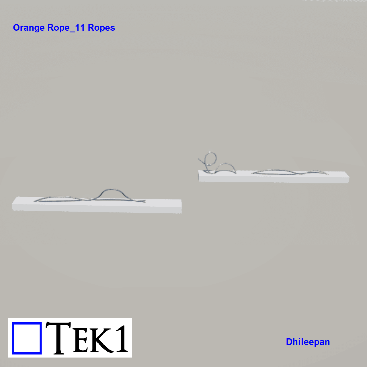
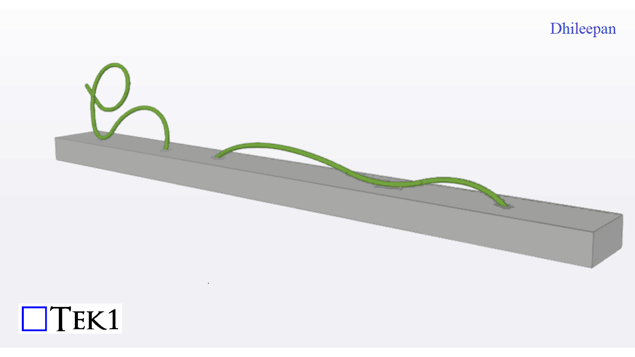
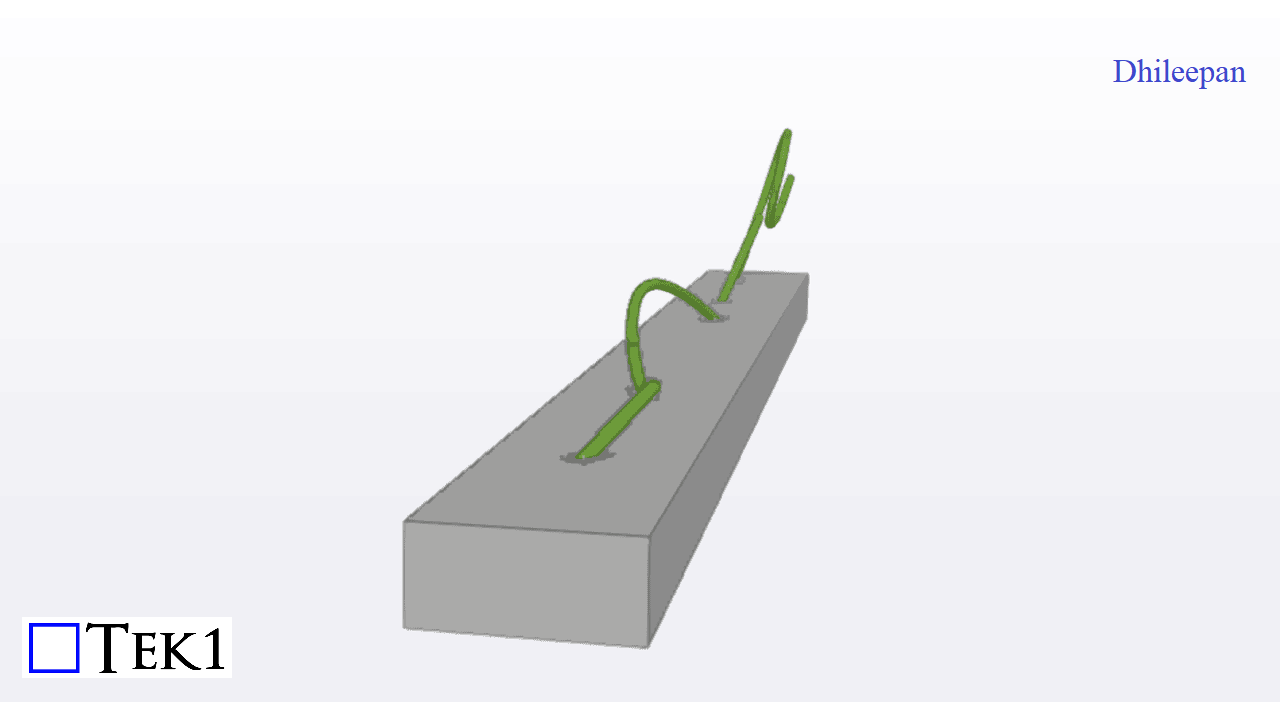
The “Orange Rope” is a series of rolled pipes placed between the piers in a bridge. This project involves a total of 11 ropes, with the following images showcasing a sample of a rope.
Challenges and Solutions
1. Converting 3D Models to 2D Fabrication Drawings
The initial input received was in the form of 3D CAD drawings, while the required output consisted of 2D drawings for fabrication. To achieve this, the 3D ropes were broken down into a series of 2D pipe members, which were then welded together to recreate the 3D structure. Each rope was divided into 4 to 5 assemblies, each containing multiple 2D pipes that, when assembled, would form the final 3D shape.
2. Welding and Alignment
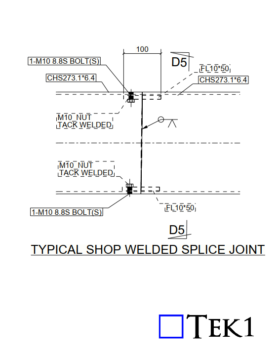
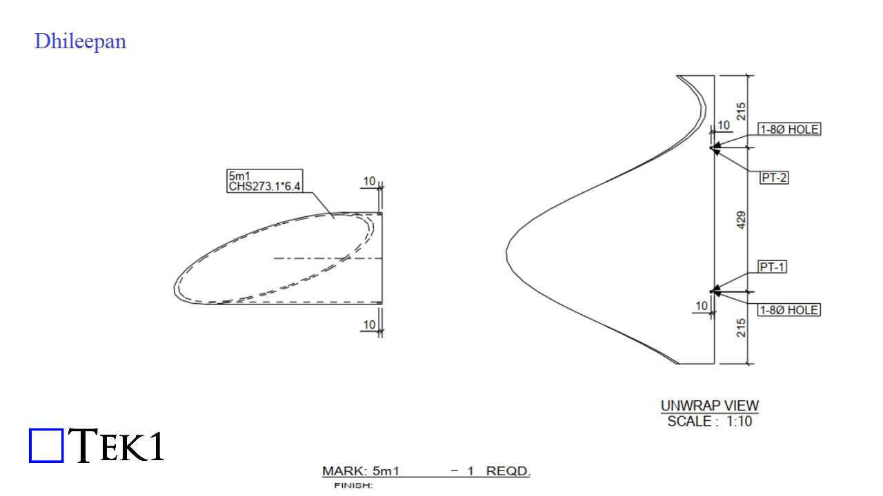
Welding each 2D pipe in the correct position to form the 3D structure presented a significant challenge. With intricate dimensions, aligning each pipe manually would be nearly impossible. To tackle this issue, a splice system was introduced. This system involved a welded plate with a nut affixed at the bottom of one pipe and a corresponding hole in the adjacent pipe. By bolting the pipes together through these holes, proper alignment was ensured before welding. Once the pipes were secured and welded, the bolts were removed, and the holes were plug-welded for a seamless finish.
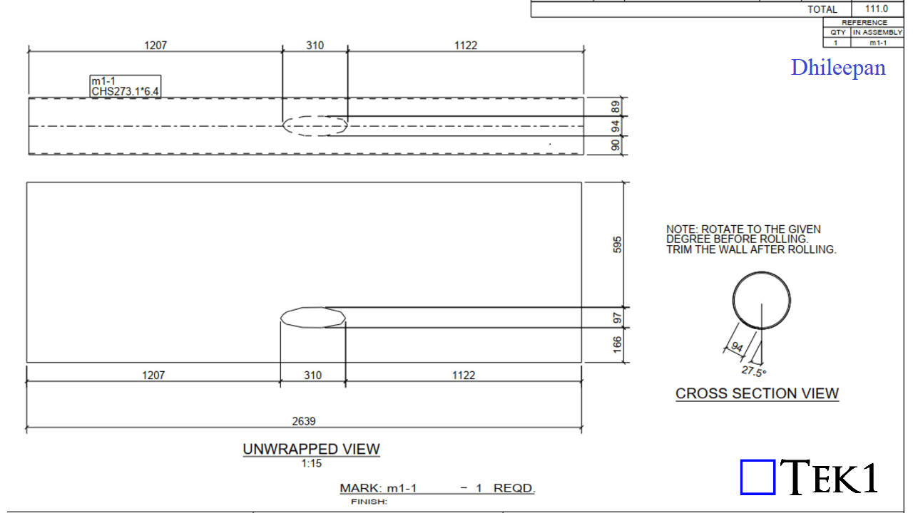
3. Asymmetrical Cuts for Base Plate Fixing
Another major challenge was the presence of asymmetrical cuts in the pipes for fixing them onto the base plates. To ensure precise cuts, unwrapped views of the pipes were provided. These unwrapped views were printed on paper at a 1:1 scale and then wrapped around the pipe. This method allowed for accurate cutting directly from the template, ensuring proper fitment and alignment during installation.
Leave a Reply