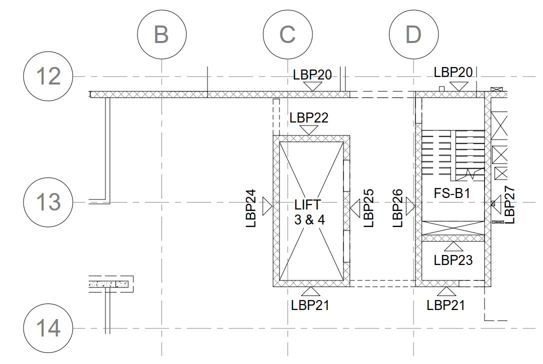
- Core plan shows the core wall, shear wall and overall slab boundary. (Only if it is provided by separate structural engineer specifically working for cores & shear walls).
- Also, it’s shown the elevation number and viewing direction. (Only if it is provided by separate structural engineer specifically working for cores & shear walls) – Refer Fig 01.
- Precast legends will be provided at title sheet.
- If too many building means, they highlighted the site key plan with current building.
- For single building area of working, they provided the key plan with elevation numbers and views. (Only if it is provided by separate structural engineer specifically working for cores & shear walls).
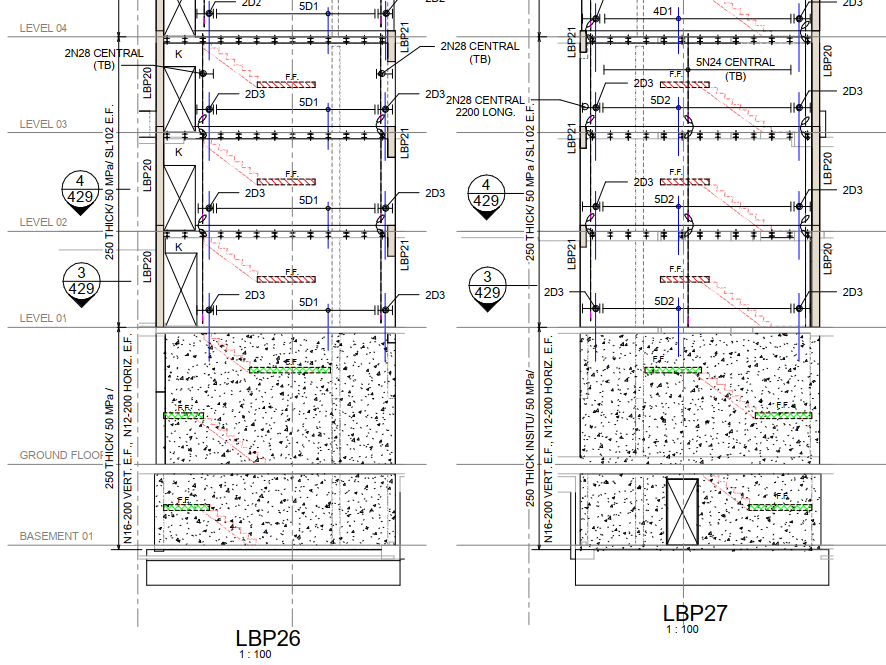
- In Core/Shear walls elevation, concerned engineer will provide below details – Refer Fig 02
- Dowel bar requirement
- Tension bar requirement
- Thickness of panel
- Grade of panel
- Reinforcement requirement (in some cases it will be given in a separate sheet)
- CIP requirement
- Wet-joint details (usually wet joint only specified. Brief details will be given in separate sheet)
- Header detail schedule type (in some cases header type only given, and will be defined in another sheet)
- In core elevation and plan, we prefer to give more importance to elevation than plan, if any issue in it we can raise RFI (Before raising RFI we have to completely analyses the discrepancy, and make a call inward and finalize the deviation. If it is not finalized then only, we can raise RFI (Request for information).
 (Fig.01) SAMPLE CORE KEY PLAN
 (Fig.02) SAMPLE CORE ELEVATION
Leave a Reply