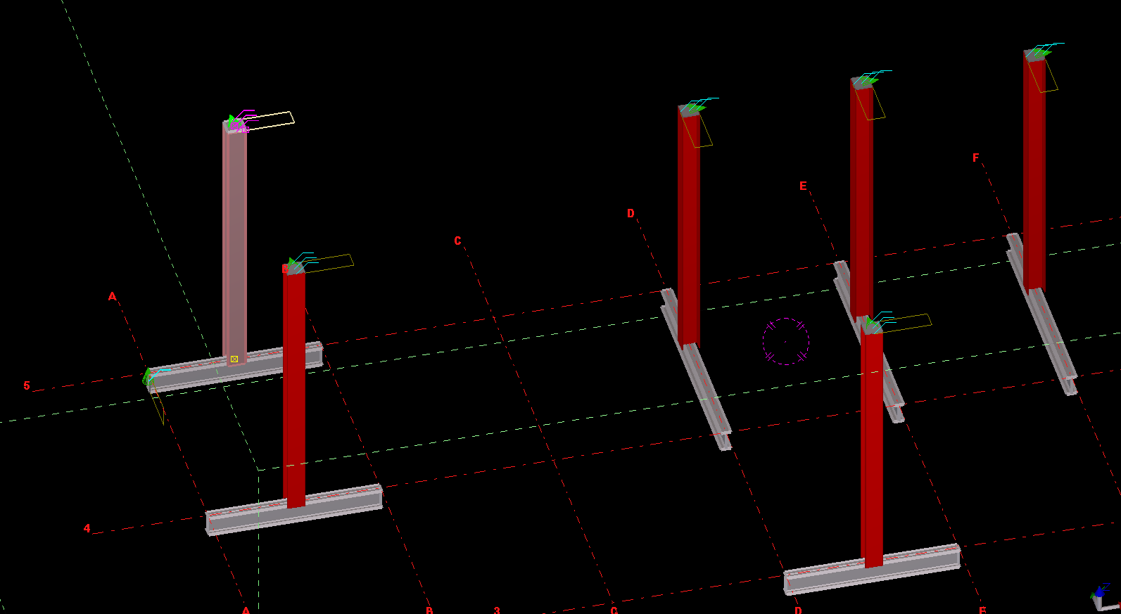
An example of us copying a column from one object, to the rest – to the rest of the beams.
What is the task at hand? We want to make the Copy Object To Object command more efficient
There is a nifty little command – little oft used in Tekla. The “Copy Object To Object” command. It’s handy, but it could be made better: all the model objects have to be selected individually. That can be a little bit of a pain. In this lesson we will create some code, using the Open API, to allow users to select multiple objects (all at once) by which the copy object to object command can be applied to.
Where is the pertinent Call in the API? I’d prefer this type of thing to be a method on the relevant ModelObject. But it’s static method in the Operation class. Here is the hello world example, straight from the documentation:
Copying Object to Object – Hello World Example:
This is fantastic! Now let us outline what we want the command to do:
What do we want our command to do?
We want the user to select an object (or group of objects).
We then want the user to select a “source” object.
We want the user to then select all objects to copy to.
The program should then use the parent object as a source, and use that as a reference to copy everything selected in step #1 to all the objects selected in step #3.
1. Ask the user to select a bunch of model objects – The objects to copy
We can use the Picker class, located in the Tekla.Structures.Model.UI namespace. And there is a handy object which thankfully has been exposed: PickObjects(Picker.PickObjectsEnum, String). This returns a ModelObjectEnumerator which we can iterate over.
2. Ask the user to select the source object:
You can get the source object in the same manner as the above code – except you would use the PickObject method instead of the PickObjects (plural) method.
3. Ask the user to select the objects to copy to:
We can use the same method used in step 1.
4. Copy from Object To Object
The rest is as easy as A-B-C:
5. Finally, we want to Redraw Views after the Copying Operation has completed
What we want to do is to select and dimension all the bolts to a particular grid line. Here’s how it should work:
* The user selects a group of bolts.
* The user selects a gridline.
* Dimensions are drawn from the Bolts to the Gridline.
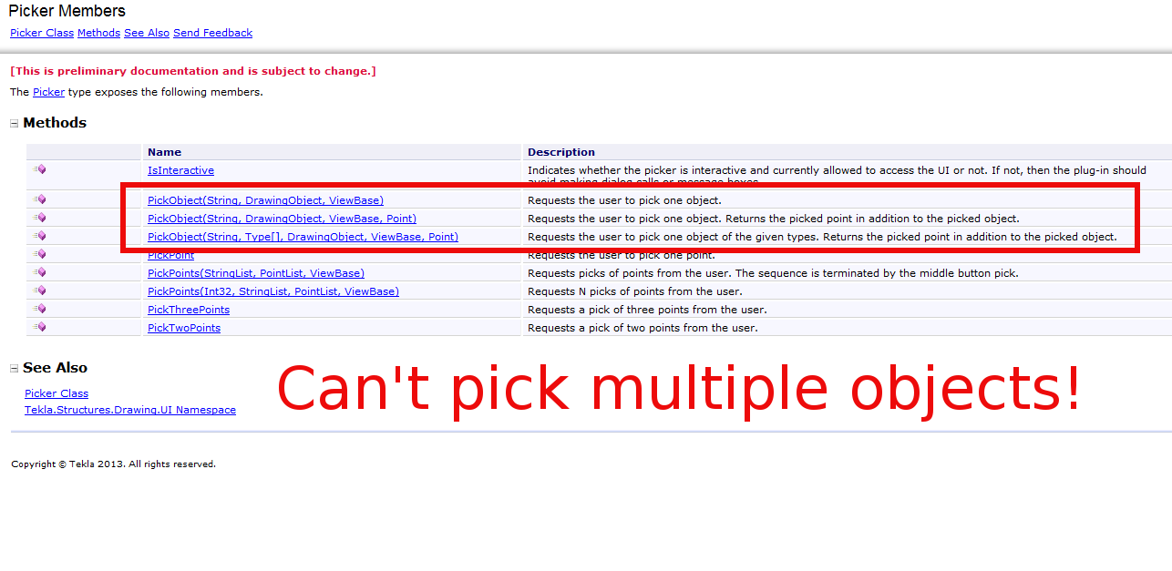
But quelle surprise – the Tekla API doesn’t expose an object which can select or pick multiple drawing objects.
What are some solutions around this problem?
We’ll we’re gonna have to be a little creative. Thankfully, Trimble have exposed the ability to programmatically obtain drawing objects. Given these objects we need to somehow filter out the stuff we want to dimension. Here are some possible ways:
We could provide a Control where we can choose and filter what objects we want to dimension, after reading/seeing it’s properties in some type of user interface (you could have a WPF application and use its fancy data binding ability + MVVM pattern + Command objects working with Service layers and Messengers) – but that would require considerable effort.
You could just select everything individually. But that would take forever.
You could extend the PickerInputWithinAView abstract method to allow you to select multiple objects.
Or you could find a way to easily filter it all. And I think I’ve found a way.
Deep in the annals of the Tekla API Reference Guide, I found that the Picker type exposes the PickTwoPoints method. And if we can pick two points, then we can certainly filter our selections.
Issues In the Algorithm We Need to Address
User picks two points.
User picks a gridline
We then filter all bolts within the bounding box of the original two picked points, and we create dimensions to the appropriate gridline. We need to understand the Drawing API.
We also need to know about saving and reverting transformation planes.
This is the hello world version of what we are trying to do, but perhaps on a scale that is a little more grand. We need some basic code on how to create dimensions.
How to Programmatically Pick Two Points
How to programmatically select a grid line
Warning – I no longer recommend this approach because it is very, very difficult to actually select a bolt. A better approach would be to select a point, and programmatically filter to get the grid line you want.
Understanding the Tekla Drawing API
Please refer to the below diagram.
An Explanation of how the Tekla API categorises its objects.
The things that you see in the drawing, are not exactly what you can see on the model. They are drawing representations of what you see in the model. If you want specific geometry based information concerning what you see in the drawing you must:
1. First get the drawing object (i.e. the drawing representation you see as a Bolt in the drawing).
2. Then you must get that same Bolt in the model.
3. You must then inquire in the model about the particular attributes or positional properties of that bolt – which is represented as a bolt in the drawing.
4. You must also bear in mind that Views etc have their own coordinate system. So if you may need to translate any differences which exist in the model to the local coordinate system of the particular view you are using. You can set and retrieve the transformation plane like so:
How to Save And Revert Transformation Planes
5. So if you need to create some dimensions, the exact lengths etc must be derived by querying the pertinent model object representations of what you see in the drawing.
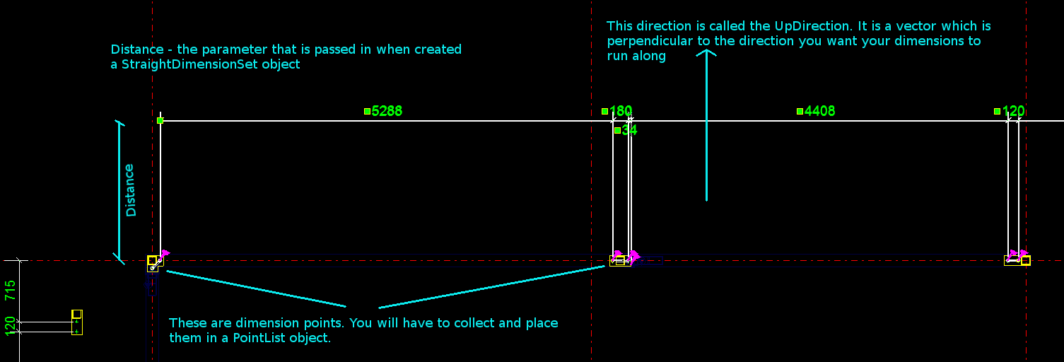
How to Create some Dimensions
The diagram provides a handy summary and visual representation of the parameters you need to pass in when creating a set of dimensions using the Tekla Open API.
How to get the drawing objects (in this case bolts) and programmatically filter them out
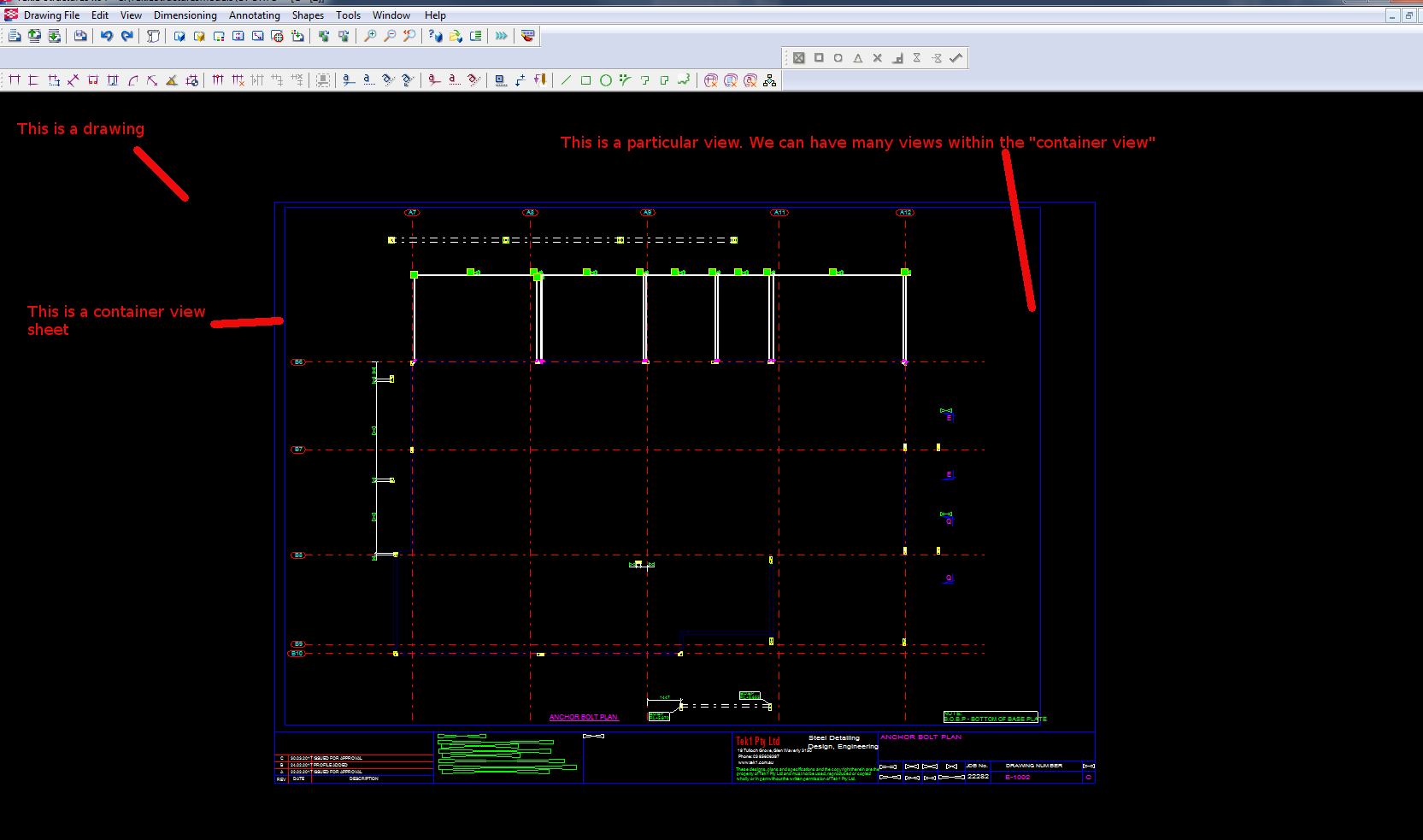
A Primer on how the Tekla.Structures.Drawing namespace is structured
Firstly you have a Drawing class. There are many types of drawing sub-classes:
Within each drawing is what is called the ConatinerView. A sheet is a container view. A container view is simply – if I were to use an everyday metaphor if you were grocery shopping – a bag which you can use to put: (i) other bags or (ii) shopping items inside. In order to get the ContainerView object, you can use the Drawing.GetSheet method – and you will be returned a ContainerView object.
Inside a container view you can typically:
* GetObjects()
* Or you can GetAllViews
* Or you can GetAllObjects of a certain type.
And within the container view, using some of the above methods you can get all sorts of DrawingObjects:
* DetailMark
* Dimensions etc
* Drawing representations of ModelObjects – like: Bolts, Connections, Grids, Gridlines, Parts, Welds etc.
Put all the elements together
If you put all the elements together, you can create some powerful little Plugins. I can’t post the full code because my boss will murder me, so I’ve done my best to teach you the key elements so you can create something powerful yourselves.
The AutoCAD .net/ObjectARX APIs have a handy feature all the pick first selection. This means that prior to running a command, the user is able to select some objects in the model. The command is then able to use these objects. The question is, how to obtain a selection of objects using the Tekla API – prior to running your plug-in?
The object of a Tekla Application is to ensure that things go smoothly on the construction site. You can see the organised chaos that is here. Avoid the real chaos. Plan ahead.
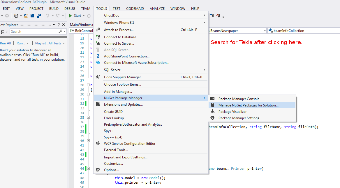
For the newbie this post shows how to set up a Tekla Project.
Let us assume that you are creating a WPF desktop Application. You could also just as easily create a console application – I often do this if I simply want a quick and dirty way to test code.
Here’s the problem. You are viewing a Tekla drawing. But you have no idea what you are looking at, or where it is. This macro will take you to that very assembly in the model. It’s actually quite handy. And here is the previous post where I made allusion to the facility (you’ll find a video demonstrating its use):
Tekla licenses are pricey. About $30k + maintenance per license. What if I told you that you needed 30-50% less licenses than you currently hold. That’s a huge cost saving, isn’t it?
If you only need 5 licenses (as opposed to 10), then you’ve saved $150k instantly, plus maintenance.
AutoCAD licenses are significantly cheaper.
But if only the work you did in AutoCAD could be transferred into Tekla? That would save you some licenses. That’s just what I’ve done here in my latest project. Now a significant portion of any modelling job can be done in AutoCAD and simply imported into Tekla.
Interoperability will also help improve the quality of your work: it’s tough finding people who are highly skilled in Tekla. What if I told you that you could use an AutoCAD draftsperson instead of someone well versed in Tekla, to do the same job? Now you have a potentially infinite pool of candidates to draw from.
I’d love to be able to help. Just call or email us.
How to Download Tekla Catalogues (or Catalogs):
You need to download the catalogue because the interop DLL connects to the catalog. Without it, we cannot verify that your profiles actually exist in Tekla.
Wouldn’t it be handy if we could pro grammatically insert reference models into Tekla? Well you can now do so quite easily. And if you want to see a video demonstration, here it is:
Here is the code which does the hard work. (You will of course add the appropriate references and directives):
This is an example of a hello world program which dimensions a beam. I found this code in the Tekla Drawing Samples folder.
You can see it in action here:
How to dimension a beam using the Tekla Open API (c#)
Let’s walk through it:
We have to get the relevant drawing.
Then we have to get the relevant part we want to dimension.
Then we get the view associated with the part.
We save our current transformation plane, and we set a new transformation plane to the particular view’s display coordinate system.
From here, get the part’s identifier and we select the ModelObject in the model itself – to get the relevant coordinates of the Beam we want to dimension.
Once we’ve used the identifier to get the Beam we are after, and to get it’s relevant parts then we create the dimension.
Remember to save back the original transformation plane.
Note: if you insert the dimension then I obtained an exception. I don’t think you need to insert dimensions when working on drawings.
Note 2: if you forget to save the transformation plane back to the original, then you will find that you dimensions will go wacky, next time you run the command. Always remember to leave things as you found them!
Note 3: You have to have the beam in the same plane as your view otherwise it won’t draw the dimension.
