
Local Steel Detailer
Some jobs need a site visit. This one need a couple of visits. Result is less problems – rather NO problem, excellent work. 20 years of detailing experience shows
(more…)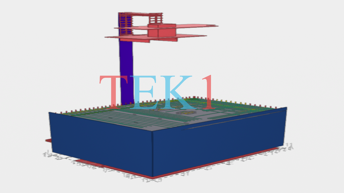
Some jobs need a site visit. This one need a couple of visits. Result is less problems – rather NO problem, excellent work. 20 years of detailing experience shows
(more…)Some jobs need a site visit. This one need a couple of visits. Result is less problems – rather NO problem, excellent work. 20 years of detailing experience shows
(more…)Some jobs need a site visit. This one need a couple of visits. Result is less problems – rather NO problem, excellent work. 20 years of detailing experience shows
(more…)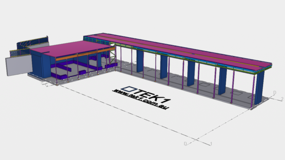
We dont blindly replicate what is on the drawing. We look at constructability, Whether any Australian standards are violated, Erection feasibility.
with huge experience and a large detailing team, Tek1 Deliver
(more…)We dont blindly replicate what is on the drawing. We look at constructability, Whether any Australian standards are violated, Erection feasibility.
with huge experience and a large detailing team, Tek1 Deliver
(more…)We dont blindly replicate what is on the drawing. We look at constructability, Whether any Australian standards are violated, Erection feasibility.
with huge experience and a large detailing team, Tek1 Deliver
(more…)

This article provides an overview of the important Australian Standards for steel detailing and serves as a practical guide for steel detailing projects in Australia.
Australian steel detailing requires more than accurately modelling beams, columns, plates and connections.
In addition, a professional steel detailer needs to understand the project documentation and the applicable Australian Standards.These standards provide an important technical framework for structural steelwork, fabrication, erection and access systems.
However, standards should always be considered together with the project’s structural drawings, specifications, contract documents and other requirements.
Therefore, understanding the applicable standards is an important part of producing accurate, coordinated and practical steel detailing documentation.
In particular, For steel detailing projects, several standards are particularly important, including AS 4100, AS/NZS 3678, AS/NZS 3679.1, AS/NZS 1163, AS/NZS 5131, AS 1657 and AS 1428.1:2021.
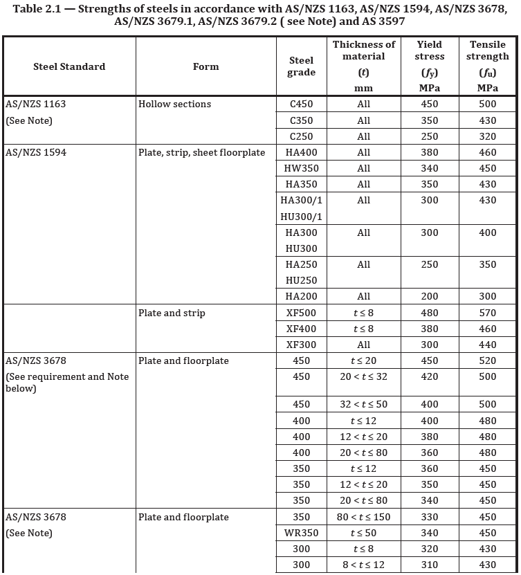
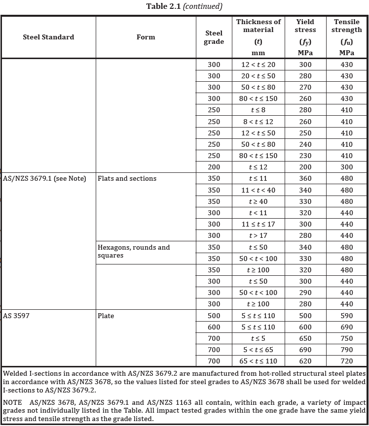
AS 4100 – Steel Structures is one of the primary standards used for structural steelwork in Australia. The current edition is AS 4100:2020.
Furthermore, standards Australia describes AS 4100:2020 as an important standard for the Australian steel sector and identifies it alongside AS/NZS 5131 as key guidance for structural steelwork.
In particular, AS 4100 is particularly important when interpreting structural design information.
Therefore, a detailer does not normally perform the structural engineer’s design, but needs to understand the design requirements sufficiently to produce accurate fabrication and erection documentation.
Typical detailing considerations include:
In addition, the structural engineer’s drawings and specifications remain the primary design inputs.
Finally, the detailer’s responsibility is to accurately translate those requirements into constructible steelwork.
AS/NZS 3678 covers structural steel, including hot-rolled plates, floorplates and slabs.
Furthermore, standards Australia identifies it as one of the key structural steel standards published as part of its steel-sector standards work program.
In particular, This standard is important when specifying and detailing fabricated steel components such as:
When preparing shop drawings, the steel grade specified by the engineer should be clearly identified.
In addition, the detailer should also ensure that the material description used in the drawings and MTO corresponds with the project requirements.
For example, a plate shown as a particular grade on the structural drawings should not be changed to another grade simply because the alternative material is readily available.
Australian steel projects commonly use hot-rolled sections such as universal beams, universal columns and angles.
AS/NZS 3679.1 – Structural steel, Part 1: Hot-rolled bars and sections is therefore highly relevant to steel detailing.
During modelling and detailing, the detailer should verify:
Furthermore, accurate member identification is especially important in Tekla Structures because incorrect profiles or grades can flow through to fabrication drawings, NC files, MTO reports and material schedules.
Hollow sections are widely used in Australian construction for columns, beams, frames, handrails, balustrades and miscellaneous steelwork.
In particular, AS/NZS 1163 covers cold-formed structural steel hollow sections.
Common hollow-section profiles include:
During the detailing process, it is important to correctly represent the section size and wall thickness specified by the engineer.
For example, an SHS column specified as SHS150 × 6 should not be modelled as SHS150 × 9 unless the change has been formally approved.
Furthermore, this is particularly important when steel members are connected to windows, doors, precast elements, concrete walls or architectural features where dimensional clearances are critical.
One of the most important standards for the fabrication and erection stage is AS/NZS 5131 – Structural steelwork – Fabrication and erection.
Furthermore, standards Australia explains that AS/NZS 5131 covers areas including fabrication, bolting and welding, surface preparation, corrosion protection, painting, galvanizing, site erection and modification of steelwork.
In particular, this standard is particularly relevant to the information shown on shop drawings.
Therefore, A professional steel detailer should consider fabrication and erection requirements when producing drawings, including:
Firstly, Drawings should provide sufficient information for the fabricator to manufacture the component correctly.
This may include:
In addition, Steelwork must also be practical to assemble on site.
Detailers should consider:
However, a connection that looks acceptable on a computer model may still be difficult or impossible to install on site.
Therefore, Good detailing requires an understanding of both fabrication and erection.
AS 1657 is particularly important for industrial steelwork, access platforms, stairs, ladders, walkways and handrails.
The standard addresses fixed means of access and safe working areas, including platforms, walkways, stairways and fixed ladders.
For steel detailers, this can affect many components, including:
When detailing stairs and handrails, the detailer must carefully check the project requirements and applicable standard requirements rather than relying on assumptions from previous projects.
Important items to verify include:
The architectural drawings, structural drawings, specifications and project requirements should all be coordinated before finalising the detailing.
AS 1428.1:2021 provides design requirements for access and mobility in new building work. In particular, it covers requirements that can affect accessible paths, ramps, stairs, landings, handrails, circulation spaces and other accessibility-related elements.
For steel detailers, this standard can be relevant when detailing commercial building stairs, ramps, handrails, balustrades, platforms and other steelwork that forms part of an accessible path of travel.
During the detailing process, the architectural and engineering drawings should be checked carefully for accessibility requirements. For example, dimensions, clearances, handrail arrangements, ramp and landing requirements may need to be coordinated with the structural steelwork.
In addition, the detailer should coordinate the steelwork with architectural layouts and project specifications to avoid conflicts with doors, walls, finishes and other building elements.
However, the steel detailer should not independently determine accessibility compliance. Instead, the applicable project requirements, architectural documentation, NCC requirements and relevant engineering information should be followed.
Therefore, where AS 1428.1:2021 applies to the project, its requirements should be considered during the steel detailing and coordination process.
Australian steel detailing is closely connected to fabrication and erection.
Before finalising the steelwork, several practical questions should be considered:
These questions can prevent costly fabrication changes and site modifications.
AS/NZS 5131 provides a framework for fabrication and erection practices, making coordination between engineering, detailing, fabrication and erection particularly important.
Modern steel detailing is often completed using 3D modelling software such as Tekla Structures.
However, software does not automatically guarantee compliance with Australian Standards.
For this reason, The detailer still needs to interpret the project documentation and apply the correct requirements.
A typical workflow may include:
Structural Drawings → Architectural Drawings → Specifications → Engineering Information → 3D Model → GA Drawings → Shop Drawings → MTO/BOM → NC Files → Fabrication → Erection
At every stage, coordination is important.
For example, if the architectural drawing shows a window in the same location as a structural column, the conflict should be identified and raised as an RFI before fabrication.
Similarly, if a structural drawing requires a particular connection but the connection cannot be fabricated or erected as shown, the issue should be referred back to the engineer rather than resolved through an unauthorised design change.
One of the most common challenges in Australian steel detailing is the difference between architectural and structural information.
Typical discrepancies include:
Therefore, the steel detailer should identify these discrepancies during the checking stage.
An effective RFI should clearly state:
As a result, this approach reduces assumptions and helps maintain a clear record of design decisions.
Australian steel detailing is not complete when the 3D model is finished.
In addition, The model must also produce accurate fabrication information and material quantities.
The MTO/BOM should correctly identify:
However, incorrect modelling can result in incorrect MTO quantities and fabrication information.Therefore, model checking should be performed before issuing the final material report.
Some common problems encountered in Australian steel detailing include:
Firstly, using the wrong material grade can create fabrication and compliance issues.
Similarly, a small difference in section size can affect connections, clearances and structural performance.
In addition, Connections must be clearly detailed in accordance with the engineer’s requirements.
However, a connection may be geometrically possible but impossible to install because the erector cannot access the bolts.
Furthermore, columns, beams and bracing may conflict with doors, windows, services or architectural finishes.
Without accurate site measurements or survey information, existing conditions can be difficult to verify. Therefore, accurate site information is important when finalizing the steelwork.
Finally, a steel detailer should not make structural design changes without appropriate engineering approval.
A professional steel detailer acts as an important link between engineering design and steel fabrication.
Therefore, the role involves much more than simply drawing steel members.
For this reason, A competent detailer should be able to:
Australian steel detailing requires a combination of technical knowledge, practical fabrication experience, attention to detail and understanding of Australian Standards.
In Particularly the Standards such as AS 4100, AS/NZS 3678, AS/NZS 3679.1, AS/NZS 1163, AS/NZS 5131, AS 1657 and AS 1428.1:2021 provide important references for different aspects of structural steelwork.
However, standards should not be viewed in isolation.
Therefore, The successful steel projects depend on coordination between the structural engineer, architect, steel detailer, fabricator and erector.
The goal of professional steel detailing is simple:
Create accurate, clear and buildable steelwork information that can be safely fabricated, delivered and erected on site.
Finally, for current editions and official information, always refer to the applicable project specifications and the official Standards Australia catalogue rather than relying on outdated or unofficial copies of standards.
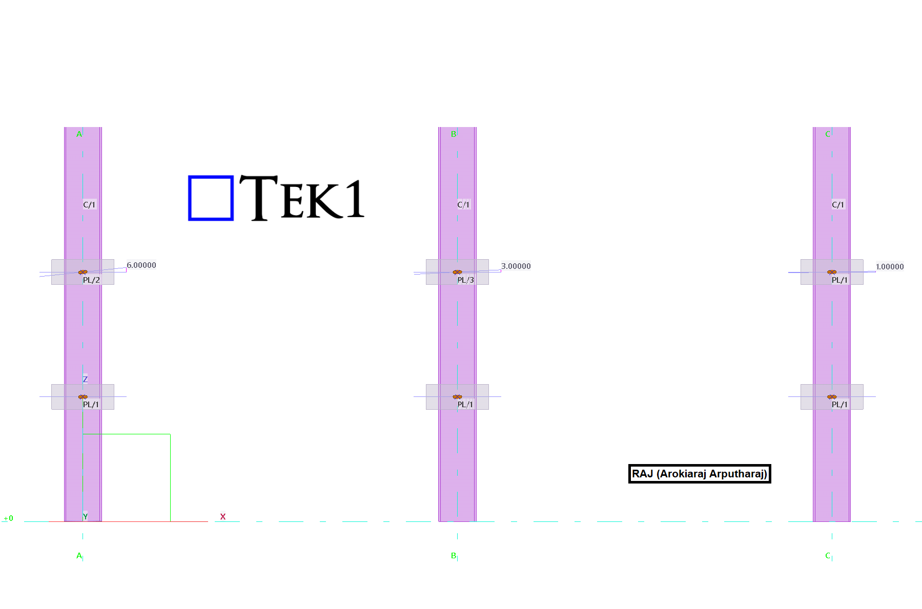
This article explains the Tekla Part Mark Issue with 1° Rotated Slotted Holes and provides a practical solution.
One common issue in Tekla Structures is assigning the same part mark to different-looking plates.
This occurs when two plates have identical dimensions, thickness, material, and slotted hole size.
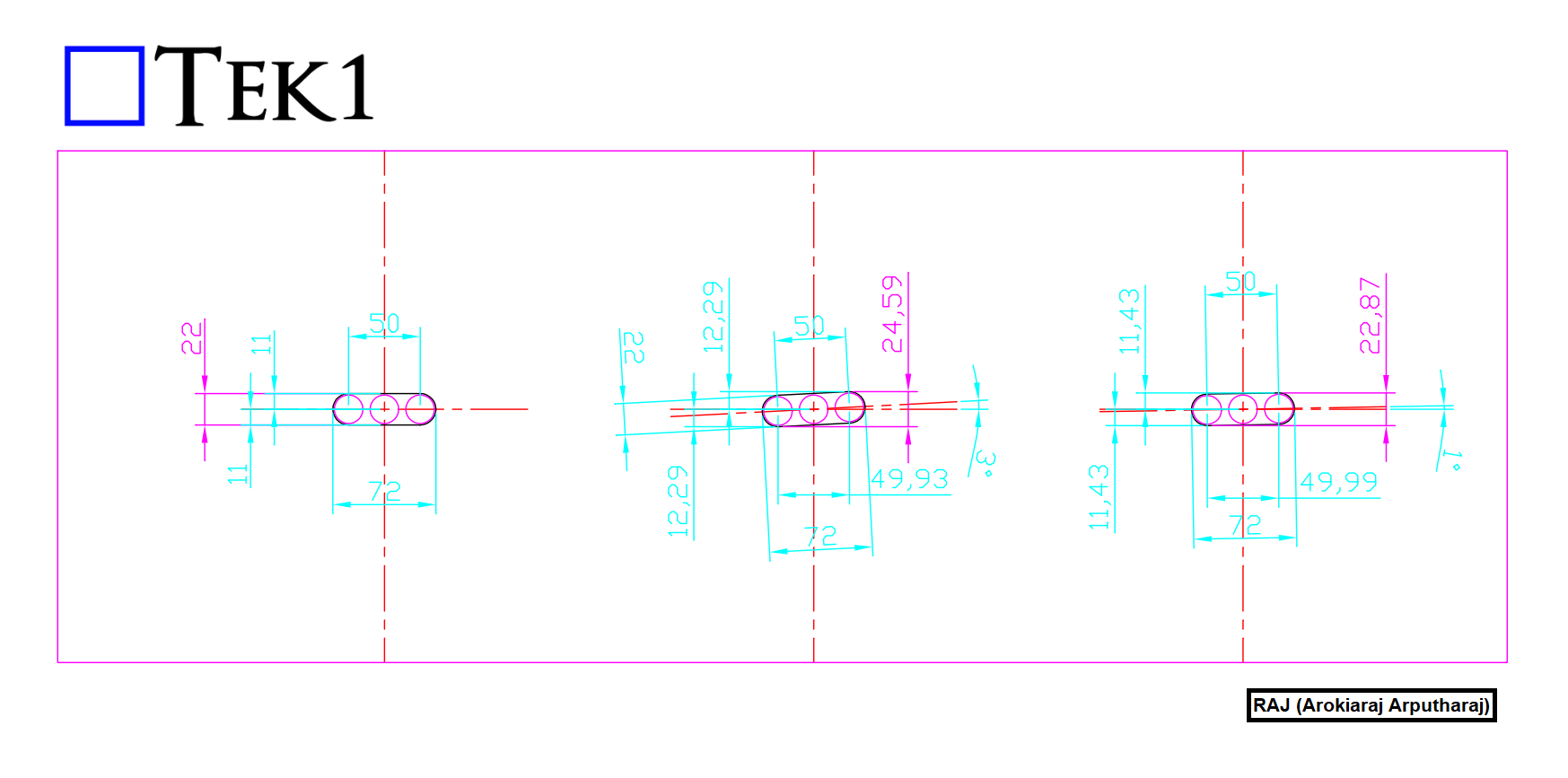
One plate contains a standard horizontal slotted hole.
The other plate has the same slot rotated by only 1°.
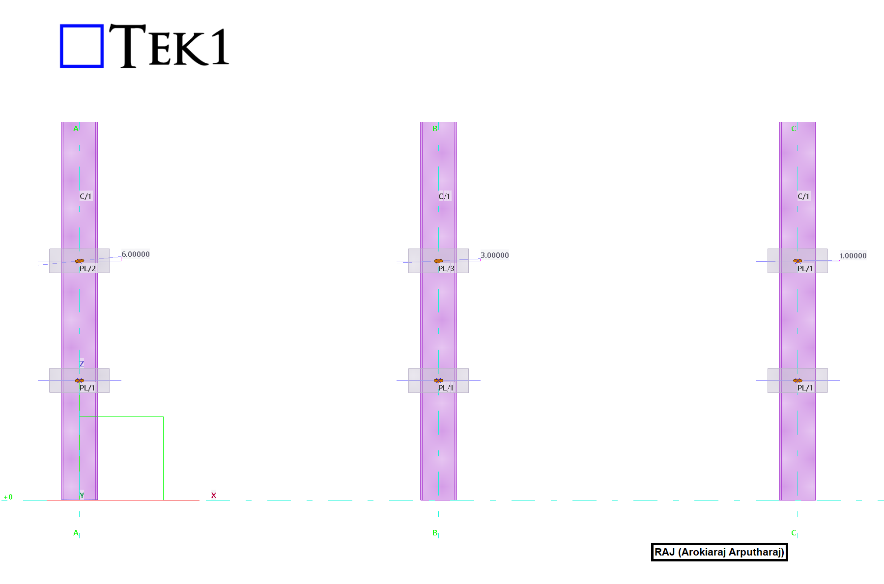
Although the slot orientations differ, Tekla evaluates both plates using its 1 mm geometry tolerance.
The 1° rotation creates a geometric difference within this tolerance.
Therefore, Tekla considers both plates identical.
As a result, Tekla automatically assigns the same part mark.
The Tekla Part Mark Issue with 1° Rotated Slotted Holes occurs because Tekla compares geometry using its default tolerance.
This behavior can create confusion during detailing and fabrication.
Detailers may expect different part marks because the slot directions are different.
Fabricators may struggle to identify the correct plate for each connection.
The issue can also affect CNC data generation.
Quality inspections may become more difficult.
Site assembly can also be affected when slot orientation is important.
Understanding the Tekla Part Mark Issue with 1° Rotated Slotted Holes helps detailers avoid unnecessary part variations.
A simple solution is to standardize the slot geometry.
Avoid creating separate plates with slightly rotated slots.
Instead, use a larger diameter horizontal slot for all similar plates.
The larger diameter slot accommodates the required installation tolerance for the 1° Rotated Slotted Holes.
Every similar plate then shares the same geometry.
All plates also receive the same part mark by design.
This approach removes unnecessary part variations.
It also maintains the required functionality and installation fit.
By following this method, you can permanently resolve the Tekla Part Mark Issue with 1° Rotated Slotted Holes.
Standardizing slotted holes provides several additional benefits.
It reduces the number of unique parts in the model.
It simplifies detailing and drawing production.
Fabrication becomes easier and more consistent.
CNC programming also becomes simpler.
The risk of manufacturing errors is reduced.
Assembly errors are less likely to occur.
Inventory management also becomes easier.
Fewer unique plate types need to be tracked.
This method is considered a best practice whenever extra slot tolerance is acceptable.
Always verify that the larger diameter slot meets project requirements.
Confirm compliance with engineering specifications before implementation.
Also ensure the connection design remains unchanged.
Using standardized slots creates cleaner Tekla models.
It improves fabrication efficiency
and reduces unnecessary detailing work.
also eliminates part mark conflicts caused by minor slot rotations.
By following this method, you can permanently resolve the Tekla Part Mark Issue with 1° Rotated Slotted Holes.
We hope this guide helps you solve the Tekla Part Mark Issue with 1° Rotated Slotted Holes in your future Tekla projects.
Tek1 believes in KISS. When things are simple, we keep it that way.
Simple for all parties
(more…)Tek1 believes in KISS. When things are simple, we keep it that way.
Simple for all parties
(more…)Tek1 believes in KISS. When things are simple, we keep it that way.
Simple for all parties
(more…)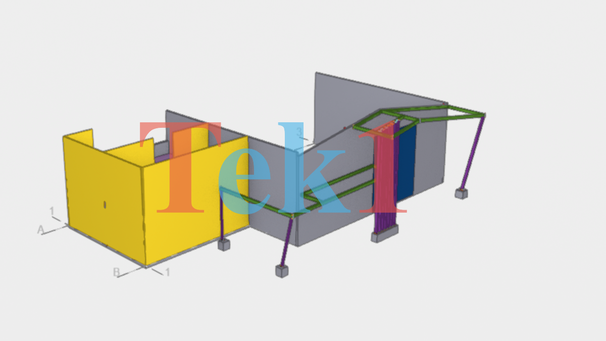
When experts handle your Steel detailing work expect that you get Zero Problems.
Fast Delivery also means, lower pricing many a times.
(more…)When experts handle your Steel detailing work expect that you get Zero Problems.
Fast Delivery also means, lower pricing many a times.
(more…)When experts handle your Steel detailing work expect that you get Zero Problems.
Fast Delivery also means, lower pricing many a times.
(more…)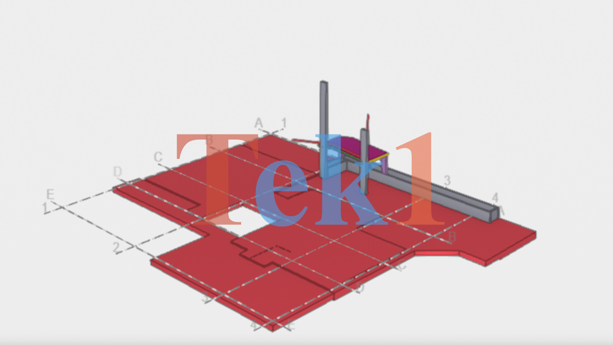
| Street Address | 9 PARK STREET WOLLONGONG |
| State | NSW |
| Country | AUSTRALIA |
| Engineer | |
| Architect | |
| Modeler | RAJ |
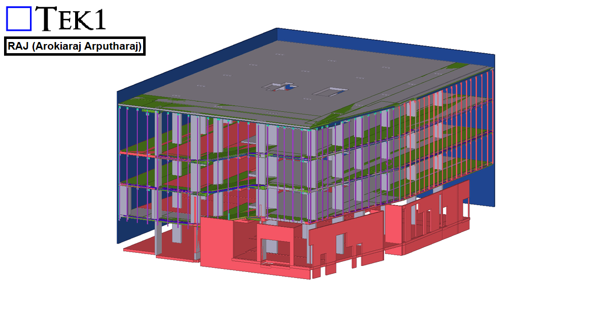
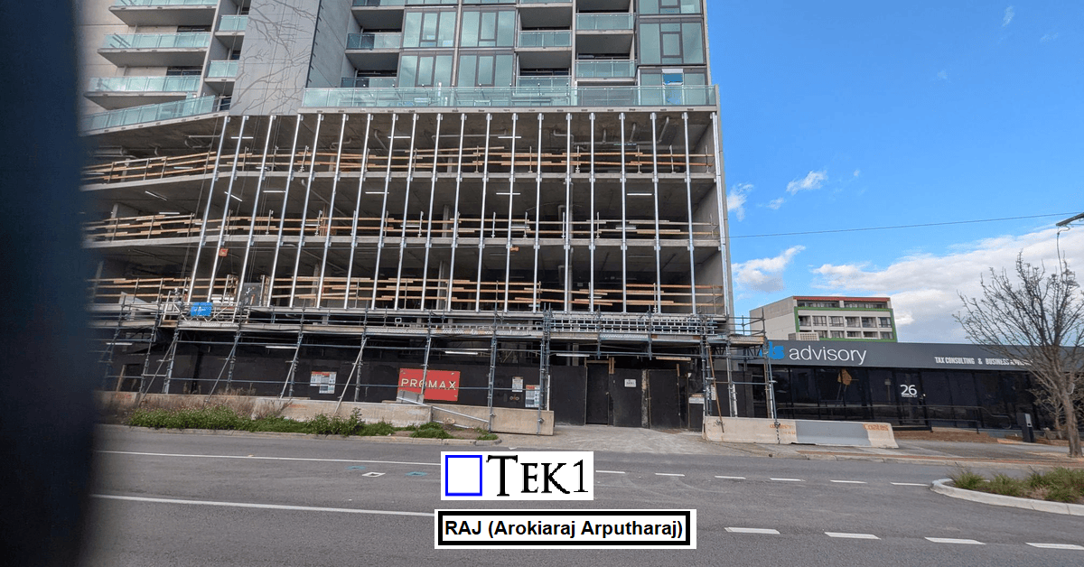
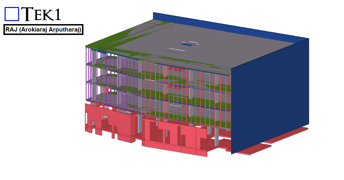
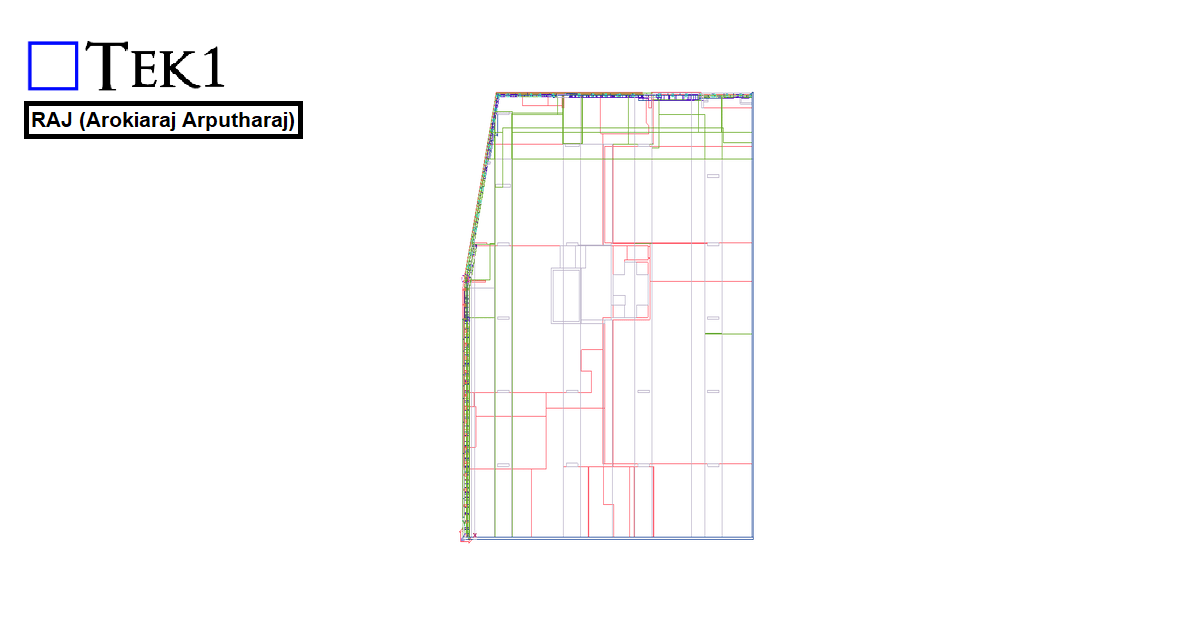
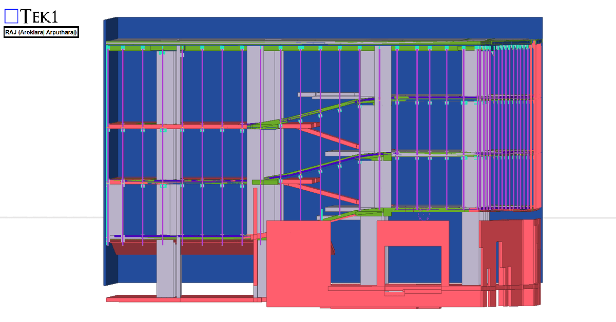
For the 27 Scott Street project, the client requested that the façade posts be installed with sufficient clearance so that the fixing anchors do not clash with the PT cable lines.
We carefully followed the client’s requirements and coordinated the design to ensure that the anchors clear the PT cable lines. The steel was successfully erected without any issues.
We would like to thank the client for giving us the opportunity to be part of this project.
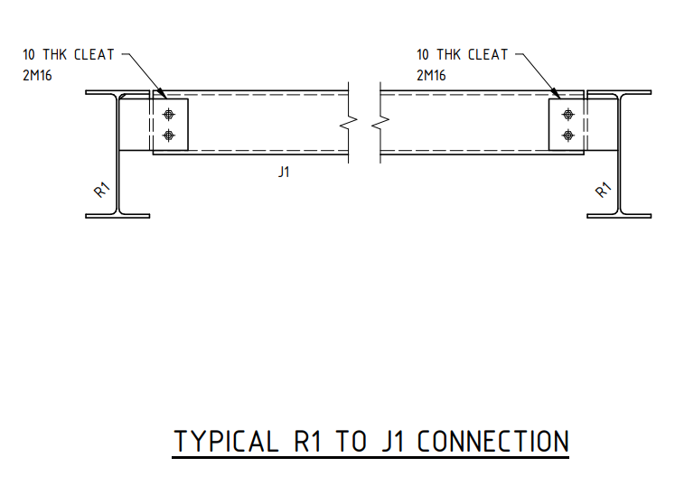
Based on this scenario, what would you propose as an alternative to balance structural performance and fabrication efficiency? Share your thoughts in the comments!
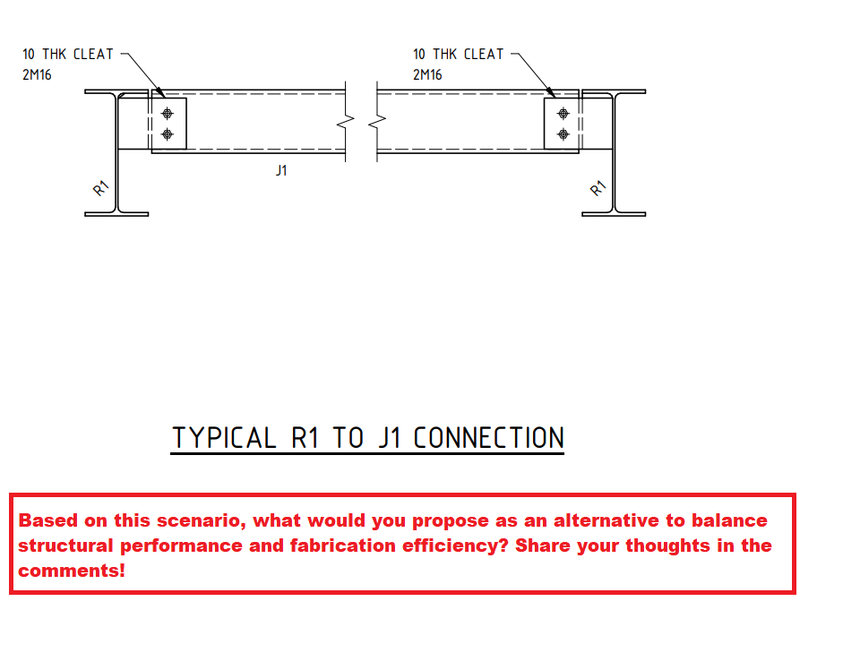
Shear connections play a crucial role in structural steelwork, ensuring the stability and strength of a framework. One common method is the extended shear plate connection, as seen in the R1 to J1 connection detail. However, this method introduces bolt eccentricity, which could impact the overall efficiency of the joint.
In the given design, the PFC (Parallel Flange Channel) shear connection is detailed using an extended shear plate. While this is a standard approach, it inherently results in increased eccentricity due to the offset load transfer through the bolts. This can lead to additional bending moments in the connection, requiring careful consideration in the design phase.
A potential improvement is to introduce a cope in the PFC section and utilize a simple shear connection instead. This modification would:
However, this approach was not accepted by the client due to fabrication ease considerations.
This case highlights a key engineering principle: design optimization vs. fabrication practicality. While structural efficiency is paramount, practical considerations such as ease of fabrication, cost, and site constraints often dictate final design choices.