This tutorial explains how to trim or extend grid lines in advanced steel.
The is the last tutorial on basic grid lines. There are other advanced options like curved grid lines. But for the time being in a beginner course this is enough.
If you can do this much confidently and correctly you will handle majority of the cases
I struggled a bit on finding the tool palette and switch it on and off. But once you know it is a no brainer. Here is a video on how to switch on and off the tool palette in advance steel
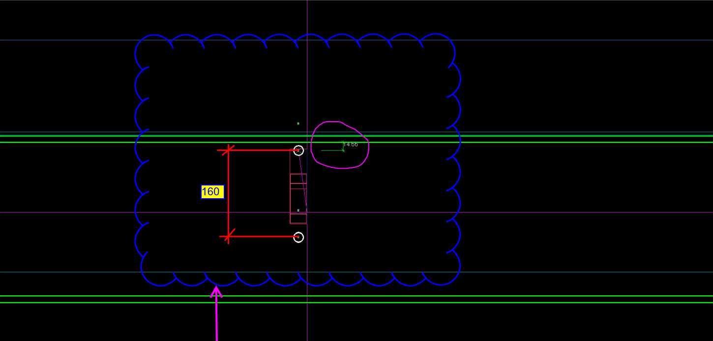
Erection Feasibility must always be considered when creating shop drawings. Consider the diagram below:
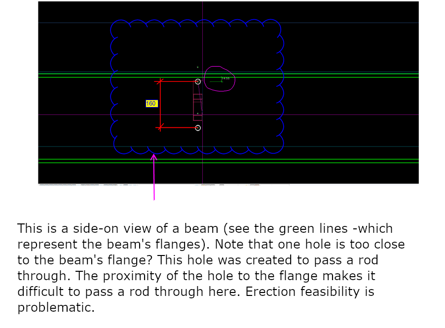
Can you spot the problem with this drawing? This is meant to be a side-on view of a beam. The green lines represent the flanges of the beam. The white circles represent holes to be drilled. What is the problem here? Consider the distances highlighted.
Pop-quiz: What is wrong with the above drawing?
(Scroll down for the answers)
(Scroll down for the answers)
(Scroll down for the answers)
The Answer:
Drilling a hole so close to the flange is not easy, neither will it be easy to pass a rod through when it is so close to the flange. You only have 14 mm till the edge of the flange. What if you used the standard pitch of 160 by route – but you’ve also got to consider erection feasibility!
Placing a hole so close to the flange will not work.